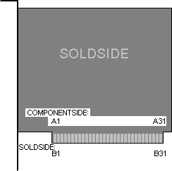
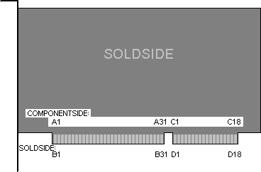
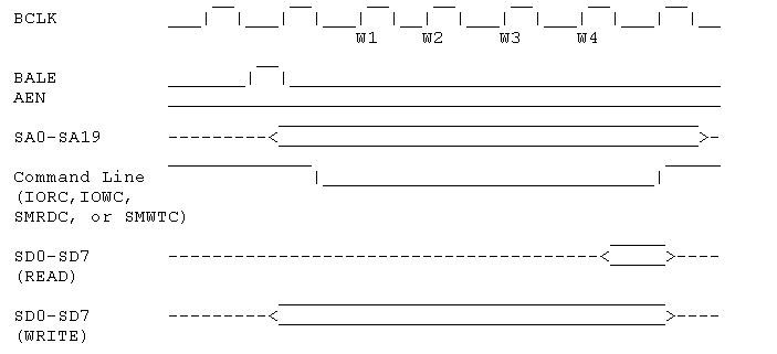
| Pin | Name | Direction | Color | Description |
| A1 | /I/O CH CK | IN | | I/O channel check; active low=parity error |
| A2 | D7 | IN/OUT | | Data bit 7 |
| A3 | D6 | IN/OUT | | Data bit 6 |
| A4 | D5 | IN/OUT | | Data bit 5 |
| A5 | D4 | IN/OUT | | Data bit 4 |
| A6 | D3 | IN/OUT | | Data bit 3 |
| A7 | D2 | IN/OUT | | Data bit 2 |
| A8 | D1 | IN/OUT | | Data bit 1 |
| A9 | D0 | IN/OUT | | Data bit 0 |
| A10 | I/O CH RDY | IN | | I/O Channel ready, pulled low to lengthen memory cycles |
| A11 | AEN | OUT | | Address enable; active high when DMA controls bus |
| A12 | A19 | OUT | | Address bit 19 |
| A13 | A18 | OUT | | Address bit 18 |
| A14 | A17 | OUT | | Address bit 17 |
| A15 | A16 | OUT | | Address bit 16 |
| A16 | A15 | OUT | | Address bit 15 |
| A17 | A14 | OUT | | Address bit 14 |
| A18 | A13 | OUT | | Address bit 13 |
| A19 | A12 | OUT | | Address bit 12 |
| A20 | A11 | OUT | | Address bit 11 |
| A21 | A10 | OUT | | Address bit 10 |
| A22 | A9 | OUT | | Address bit 9 |
| A23 | A8 | OUT | | Address bit 8 |
| A24 | A7 | OUT | | Address bit 7 |
| A25 | A6 | OUT | | Address bit 6 |
| A26 | A5 | OUT | | Address bit 5 |
| A27 | A4 | OUT | | Address bit 4 |
| A28 | A3 | OUT | | Address bit 3 |
| A29 | A2 | OUT | | Address bit 2 |
| A30 | A1 | OUT | | Address bit 1 |
| A31 | A0 | OUT | | Address bit 0 |
| B1 | GND | | | Ground |
| B2 | RESET | OUT | | Active high to reset or initialize system logic |
| B3 | +5V | | | +5 VDC |
| B4 | IRQ2 | IN | | Interrupt Request 2 |
| B5 | -5VDC | | | -5 VDC |
| B6 | DRQ2 | IN | | DMA Request 2 |
| B7 | -12VDC | | | -12 VDC |
| B8 | /NOWS | IN | | No WaitState |
| B9 | +12VDC | | | +12 VDC |
| B10 | GND | | | Ground |
| B11 | /SMEMW | OUT | | System Memory Write |
| B12 | /SMEMR | OUT | | System Memory Read |
| B13 | /IOW | OUT | | I/O Write |
| B14 | /IOR | OUT | | I/O Read |
| B15 | /DACK3 | OUT | | DMA Acknowledge 3 |
| B16 | DRQ3 | IN | | DMA Request 3 |
| B17 | /DACK1 | OUT | | DMA Acknowledge 1 |
| B18 | DRQ1 | IN | | DMA Request 1 |
| B19 | /REFRESH | IN/out | | Refresh |
| B20 | CLOCK | OUT | | System Clock (67 ns, 8-8.33 MHz, 50% duty cycle) |
| B21 | IRQ7 | IN | | Interrupt Request 7 |
| B22 | IRQ6 | IN | | Interrupt Request 6 |
| B23 | IRQ5 | IN | | Interrupt Request 5 |
| B24 | IRQ4 | IN | | Interrupt Request 4 |
| B25 | IRQ3 | IN | | Interrupt Request 3 |
| B26 | /DACK2 | OUT | | DMA Acknowledge 2 |
| B27 | T/C | OUT | | Terminal count; pulses high when DMA term. count reached |
| B28 | ALE | OUT | | Address Latch Enable |
| B29 | +5V | | | +5 VDC |
| B30 | OSC | OUT | | High-speed Clock (70 ns, 14.31818 MHz, 50% duty cycle) |
| B31 | GND | | | Ground |
| C1 | SBHE | IN/OUT | | System bus high enable (data available on SD8-15) |
| C2 | LA23 | IN/OUT | | Address bit 23 |
| C3 | LA22 | IN/OUT | | Address bit 22 |
| C4 | LA21 | IN/OUT | | Address bit 21 |
| C5 | LA20 | IN/OUT | | Address bit 20 |
| C6 | LA18 | IN/OUT | | Address bit 18 |
| C7 | LA17 | IN/OUT | | Address bit 17 |
| C8 | LA16 | IN/OUT | | Address bit 16 |
| C9 | /MEMR | IN/OUT | | Memory Read (Active on all memory read cycles) |
| C10 | /MEMW | IN/OUT | | Memory Write (Active on all memory write cycles) |
| C11 | SD08 | IN/OUT | | Data bit 8 |
| C12 | SD09 | IN/OUT | | Data bit 9 |
| C13 | SD10 | IN/OUT | | Data bit 10 |
| C14 | SD11 | IN/OUT | | Data bit 11 |
| C15 | SD12 | IN/OUT | | Data bit 12 |
| C16 | SD13 | IN/OUT | | Data bit 13 |
| C17 | SD14 | IN/OUT | | Data bit 14 |
| C18 | SD15 | IN/OUT | | Data bit 15 |
| D1 | /MEMCS16 | IN | | Memory 16-bit chip select (1 wait, 16-bit memory cycle) |
| D2 | /IOCS16 | IN | | I/O 16-bit chip select (1 wait, 16-bit I/O cycle) |
| D3 | IRQ10 | IN | | Interrupt Request 10 |
| D4 | IRQ11 | IN | | Interrupt Request 11 |
| D5 | IRQ12 | IN | | Interrupt Request 12 |
| D6 | IRQ13 | IN | | Interrupt Request 13 |
| D7 | IRQ14 | IN | | Interrupt Request 14 |
| D8 | /DACK0 | OUT | | DMA Acknowledge 0 |
| D9 | DRQ0 | IN | | DMA Request 0 |
| D10 | /DACK5 | OUT | | DMA Acknowledge 5 |
| D11 | DRQ5 | IN | | DMA Request 5 |
| D12 | /DACK6 | OUT | | DMA Acknowledge 6 |
| D13 | DRQ6 | IN | | DMA Request 6 |
| D14 | /DACK7 | OUT | | DMA Acknowledge 7 |
| D15 | DRQ7 | IN | | DMA Request 7 |
| D16 | +5 V | | | |
| D17 | /MASTER | IN | | Used with DRQ to gain control of system |
| D18 | GND | | | Ground |


