Find your manual in our Disassemble database ...

     HOME      | Mobile phones | Laptops nad netbooks | Desktop PC | Monitors and screens |      OTHER

Can't find what you need? Request a disassembly manuals and we will try to locate it and add it to our database.

 » Pinout.net - Disassemble Database »  LCD screen in a Toshiba Satellite A355 A355D


If you like this manual recomend it to your friends...


STEP 1

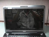
Turn off the laptop and remove the battery.

There are four rubber screw seals on the screen bezel.
Remove all four seals and screws found under them.


STEP 2

You can remove the screw seal with a sharp object or small flat head screwdriver.
Glue seals somewhere on the bezel so they don't get lost.


STEP 3

Start separating the screen bezel from the display cover on the side.


STEP 4

You can use a guitar pick or another piece of soft plastic to separate the bezel.
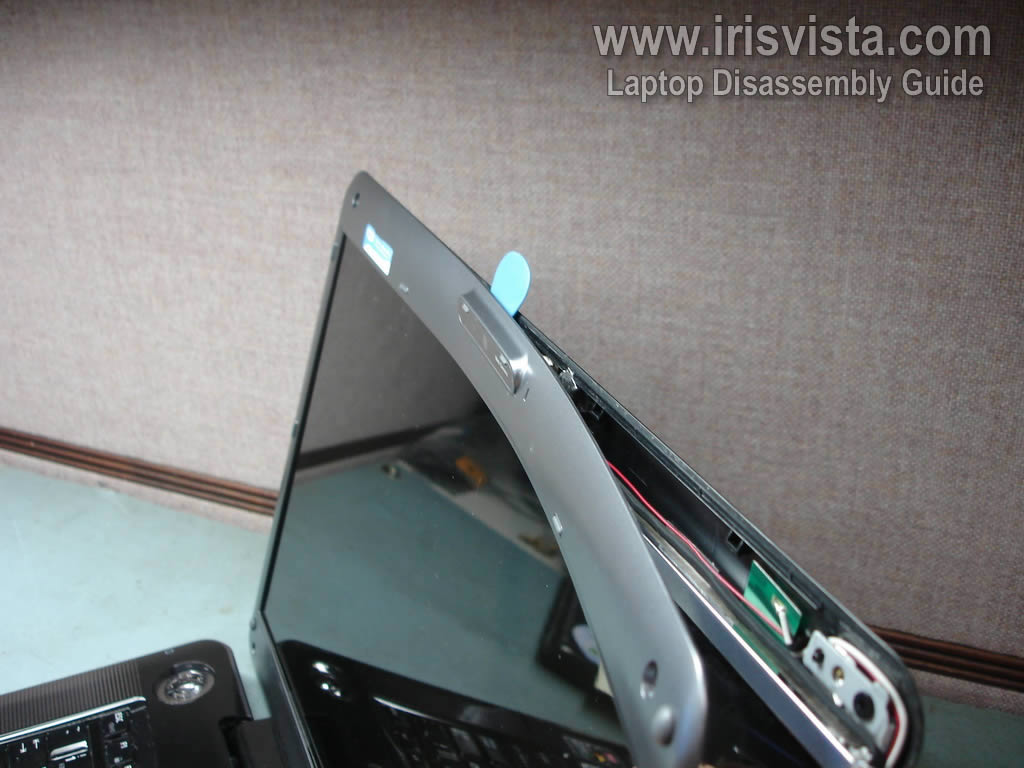
   

STEP 5

Continue separating the screen bezel on the top of the display panel.


STEP 6

Use a screwdriver to separate the bottom part of the bezel.
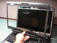
   

STEP 7

The screen bezel has been removed.
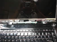
   

STEP 8

The screen inverter board is mounted below the screen.
I'm not replacing the inverter board so I'll leave it attached to the display cover.

Remove the screen backlight cable from the right side of the inverter board.


STEP 9

Remove eight screws securing display hinges.

STEP 10

Remove two screws securing the LCD screen on the top.


STEP 11

The wireless antenna and webcam cables on the right side of the display panel are secured by three foil strips.
Unglue foil strips as it shown on the picture.


STEP 12

Do the same with four foil strips on the left side of the display panel.


STEP 13

Disconnect the black cable from the web camera module.
You will not be able to separate the screen from the cover without disconnecting this cable.


STEP 14

Separate the display cover from the LCD screen assembly.


STEP 15

Now you can access the video cable connection on the back of the screen.


STEP 16

Disconnect video cable from the connector on the LCD screen.


STEP 17

Remove three screws from both sides of the LCD screen.
These screws secure the LCD screen to the mounting brackets.


STEP 18

Rem


If you like this manual recomend it to your friends...

Search for Disassembly manuals
PinoutMaster team 2005 - 2024 Service manuals - Car Audio Unlock- Elemetnt Datasheets-