|
Can't find what you need? Request a disassembly manuals and we will try to locate it and add it to our database.
» Pinout.net - Disassemble Database » Toshiba Satellite 5105 guide. Removing and replacing video
If you like this manual recomend it to your friends...
| | |
| |
| |
|
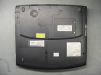 |
STEP 1
Turn the laptop upside down.
Remove the battery.
Remove one screw securing the hard drive cover and remove the hard drive.
Remove six screws securing the memory cover, the modem cover, the modem/LAN jacks cover and remove all covers.
|
| |
Need spare parts for Satellite 5105 laptop? Search here. |
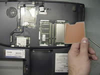 |
STEP 2
Remove the memory cards.
|
| |
|
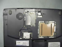 |
STEP 3
Remove two screws securing the modem card to the system board.
Disconnect the LAN jack cable on the system board.
Lift off the modem card and the LAN jack assembly.
|
| |
|
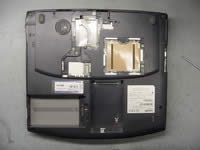 |
STEP 4
Remove all marked screws on the bottom of the laptop.
|
| |
|
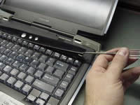 |
STEP 5
Turn the notebook right side up.
Insert a thin object under the securing strip and lift it up.
Be careful, it may be very tight.
|
| |
|
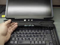 |
STEP 6
Remove the keyboard securing strip.
|
| |
|
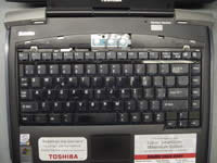 |
STEP 7
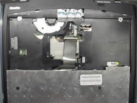
Remove two screws securing the keyboard.
Turn the keyboard over and place it on the palmrest.
|
| |
|
 |
STEP 8
Disconnect the keyboard flat cable on the system board.
Remove the keyboard.
|
|
|
STEP 9
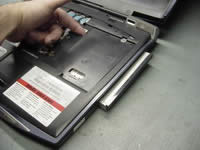
Remove one screw securing the DVD drive.
|
|
| |
|
 |
STEP 10
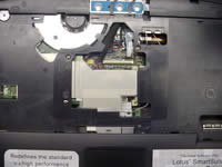
Slide the DVD drive out of the laptop base and remove it.
|
| |
|
 |
STEP 11
Remove one screw securing the metal plate over the VGA board connectors.
|
| |
|
 |
STEP 12
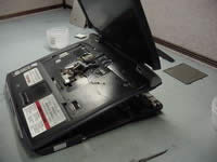
Remove three screws securing the top cover.
Disconnect the speaker cables, the membrane swich cable, the front panel cable, the touchpad cable and the LCD/FL inverter cables.
|
| |
|
 |
STEP 13
Lift off the LCD/top cover assembly.
|
| |
|
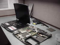 |
STEP 14
Remove the LCD/top cover assembly.
|
| |
|
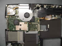 |
STEP 15
Remove one screw securing the metal brace over the hard drive connector.
Lift off the brace.
|
| |
|
 |
STEP 16
Lift off the video (VGA) board to disconnect if from the system board.
|
|
| |
If you like this manual recomend it to your friends...
Search for Disassembly manuals
PinoutMaster team 2005 - 2025
Service manuals -
Car Audio Unlock-
Elemetnt Datasheets-
|


